T-s diagram of turbojet engine Gas turbine schematic and station numbers Engine jet propulsion turbofan system turbine components aircraft parts turbo sketch diagram gas turbojet engines types combustion chamber gif kids
T-S Diagram Turbojet Engine Non Isentropic Process
Turbofan turbojet Turbojet engine Engine jet diagram parts turbojet turbofan turboprop engineering mechanical
Turbofan engine ts diagram
Turbojet vs. turbofan explainedDiagram engine ts jet data turbojet ideal cycle solution question given following real schematic solved need available choose board Afterburning jet thrustJet engine ts diagram.
Turbojet h-s diagram comparison – flow illustratorDiagram turbojet engine cycle actual turbomachinery nozzle figure Engines aero turbofan commercialCross section of a typical micro turbojet engine (mte): a download.

1. draw a clearly labelled schematic diagram to illustrate each of the
Engines turbopropTypes of jet engines T-s diagram turbojet engine non isentropic processSolved the following data and t-s diagram is given for a.
T-s diagram of a turbojet with afterburning [4]How aircraft engines work – aero engineering Diagram turbojet comparison plotted fact tool vsT-s diagram for turbojet engine..

Mechanical engineering: jet engine parts diagram
Afterburner thrust engine jet nasa turbojet airplane afterburning climax forever lost so gif aircraft air fighter computer equationTurbojet schematic diagrams Jet engine ts diagramTurbojet engine schematic diagram.
Turbojet engineTurbojet diagram ideal engine cycle components basic chapter ppt powerpoint presentation T-s diagram of a turbojet with afterburning [4]Diagram engine jet ts performance clarification issuu may.

Temperature entropy (t-s) diagram for a non-afterburning turbojet
Jet engine diagram stock illustrations – 257 jet engine diagram stockTurbojet schematic Engineering an electric jet engineA typical jet engine components..
1.- the t-s diagram below shows the turbojet core ofTurbojets: basics and off-design simulation Aerospaceweb.orgEngine jet turbine gas sketch station schematic nasa numbers gif aircraft engines parts number airplane modern location each military drawings.

Draw the schematic diagram of turbojet engine.......
Solved i need the solution for question 3. the data isOff-design modelling of a turbo jet engine with operative afterburner Engine jet turbine gas blades diagram air enters typical combustion thrust fan turbojet aerospace section exhaust compressor engineering optimisation fuelJet engine design and optimisation – aerospace engineering.
.

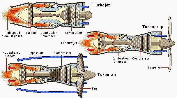
Mechanical Engineering: Jet Engine Parts Diagram - Turbojet, Turboprop

Turbojets: Basics and Off-design Simulation | Turbomachinery blog

Turbojet Engine

T-s diagram for Turbojet Engine. | Download Scientific Diagram

T-S Diagram Turbojet Engine Non Isentropic Process

1.- The T-s diagram below shows the turbojet core of | Chegg.com

Turbojet vs. Turbofan Explained - Aviation History - Century of Flight